

55030113
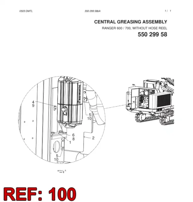
LUBRICATION DIAGRAM
The 550 301 13 LUBRICATION DIAGRAM is a key piece for getting grease or oil to the right spots on your rig. This component, part number 550 301 13, precisely meters lubricant, keeping friction down and preventing premature wear on critical moving parts. It's essential for smooth, reliable operation.
Description
550 301 13 LUBRICATION DIAGRAM is one of those components that's absolutely key for getting grease or oil exactly where it needs to be, especially on the feed beam, the rotation unit, or even the drifter's front head. It’s not just a simple fitting…
Full Technical Description
550 301 13 LUBRICATION DIAGRAM is one of those components that's absolutely key for getting grease or oil exactly where it needs to be, especially on the feed beam, the rotation unit, or even the drifter's front head. It’s not just a simple fitting; usually, it’s a metering valve or a distribution block designed to split and deliver a precise shot of lubricant to multiple points. This ensures all those pins, bushings, and sliding surfaces get their regular feed, keeping friction down and preventing premature wear.
When this part starts to give up the ghost, you’ll usually notice it first through other symptoms. Maybe a bearing on the feed motor starts running hotter than it should, or you hear a distinct squeak from a pivot point that used to be quiet. Sometimes, the auto-lube system pressure might fluctuate wildly, or you might even get a 'low lube pressure' alarm if it’s completely blocked or leaking internally. What often happens is that one specific point, like a feed chain roller or a drifter guide, just stops getting its grease, leading to accelerated wear and eventually, a seized component.
When you're swapping one of these out, it’s not just a simple bolt-on job. Always take a good look at the lines connecting to it – check for kinks, blockages, or any signs of previous leaks that might have starved the system. A common oversight is not properly purging the air from the new component and its lines after installation, which can lead to initial starvation and a false sense of security. Make sure the system cycles a few times to push fresh grease through everything.
Applications
- Underground drilling jumbos
- Mining and tunneling
- Hydraulic control systems
- Rock drilling spare parts
Specifications
| Brand | Sandvik |
|---|---|
| Machine Type | RANGER 700-2 |
| Assembly | CENTRAL GREASING ASSEMBLY |
Used on machines
Brand
All Sandvik partsRelated parts
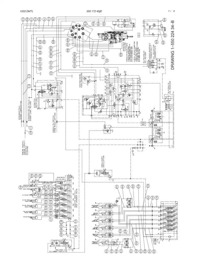
HYDRAULIC DIAGRAM
55017245
Similar part
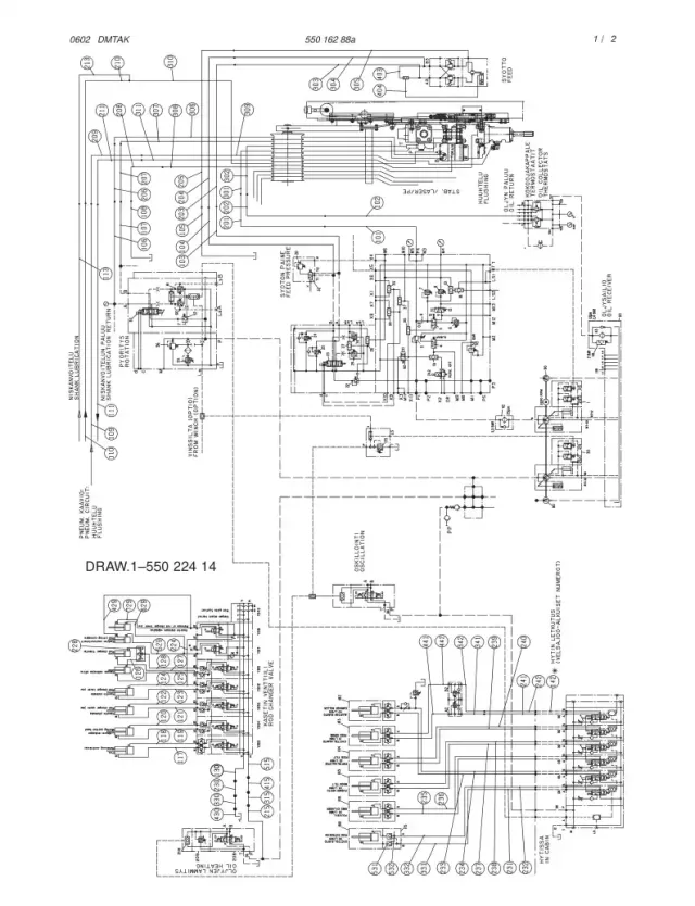
HYDRAULIC DIAGRAM
55016289
Similar part
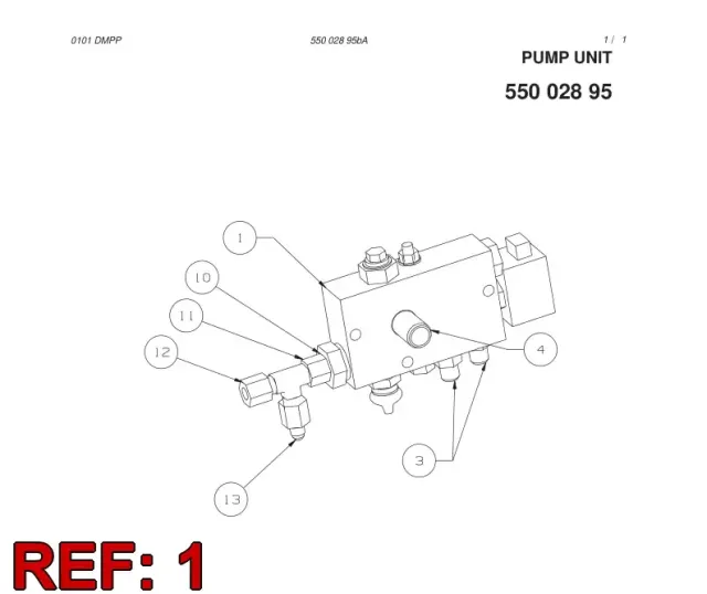
LUBRICATION PUMP
88760719
Similar part
LUBRICATION DIAGRAM
55023914
Similar part
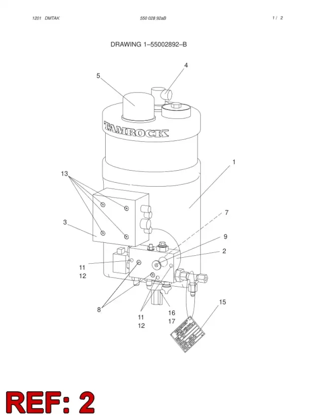
LUBRICATION PUMP ASSY
55002895
Similar part
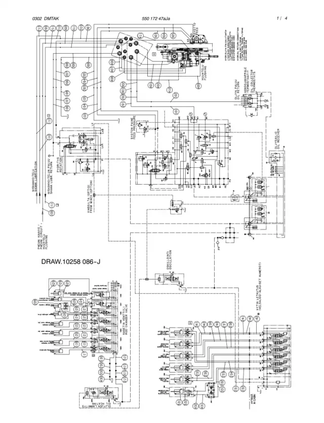
HYDRAULIC DIAGRAM,BOOM (1-550
55017247bB
Similar part
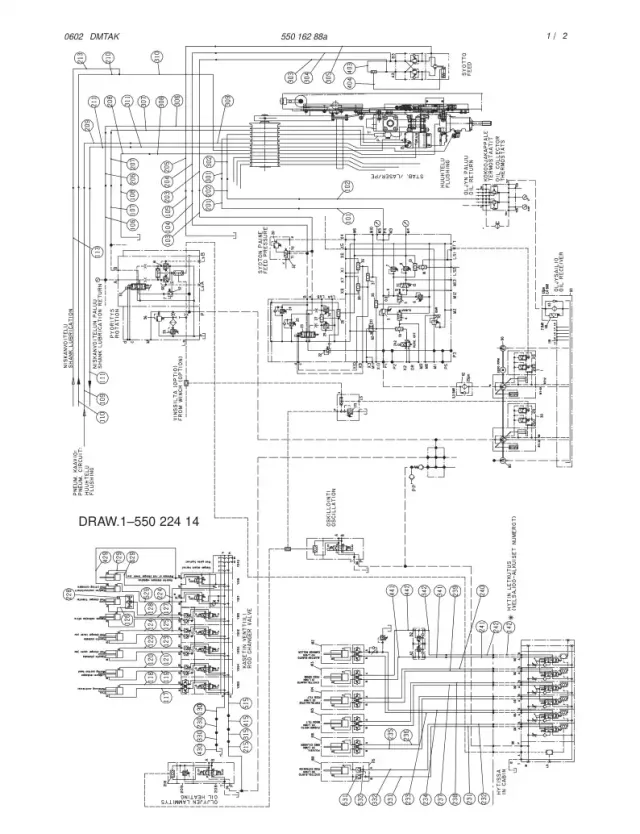
HYDRAULIC DIAGRAM,BOOM (1-550
55016288dC
Similar part
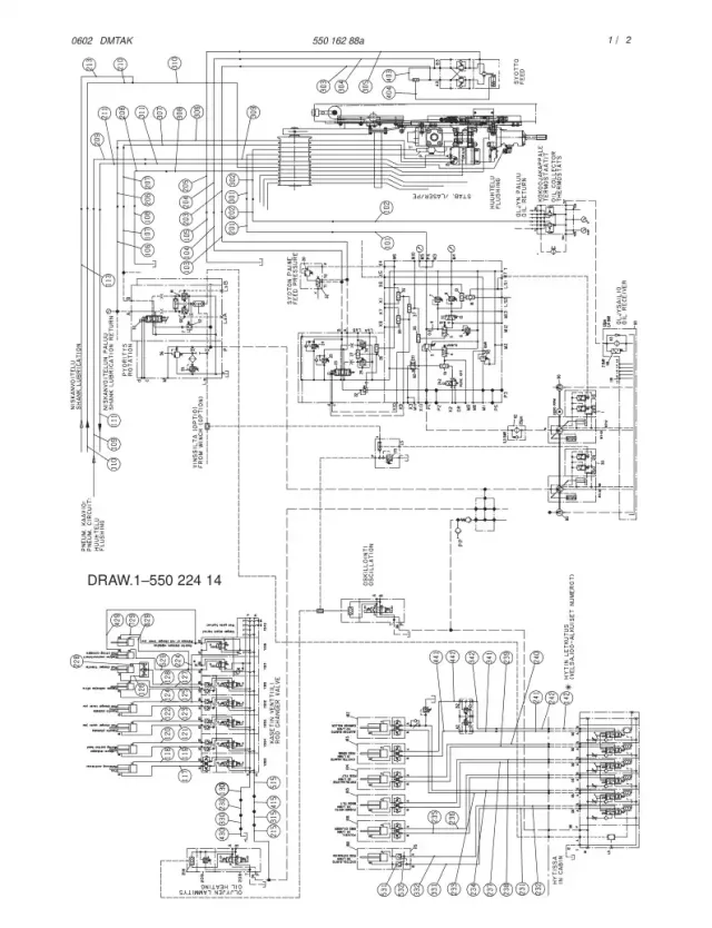
HYDRAULIC DIAGRAM,BOOM (1-550
55016288dD
Similar part
Customer Reviews
No reviews yet.
Reviews come from verified buyers: customers whose quotation for this part was accepted.
How to get LUBRICATION DIAGRAM 55030113
Jumbosan supplies LUBRICATION DIAGRAM 55030113. Choose the way that suits you.
Send a quote request form
Fill in the short form with the quantity and your company details. We reply with availability and lead time.
Contact us by email
Email [email protected] with the part number and the quantity you need.
Message us on WhatsApp
Send the part number to +90 543 279 89 81 on WhatsApp and a salesperson replies in the chat.
Send your list to the AI quote page
Upload a PDF, photo or spreadsheet of part numbers. The AI reads it and builds the request for you, which suits long lists.